[diagram] wiki timing diagram Solved draw timing diagrams for the circuits in figures 8.43 Solved for the circuit below, draw the timing diagram of draw a timing diagram for the circuit 2.24
For the following circuit complete the timing | Chegg.com
555 timer circuit board diagram Timing assuming outputs qi cycles Solved 1- draw the timing diagram for the following circuit
Solved 4. a. consider following circuit. draw the timing
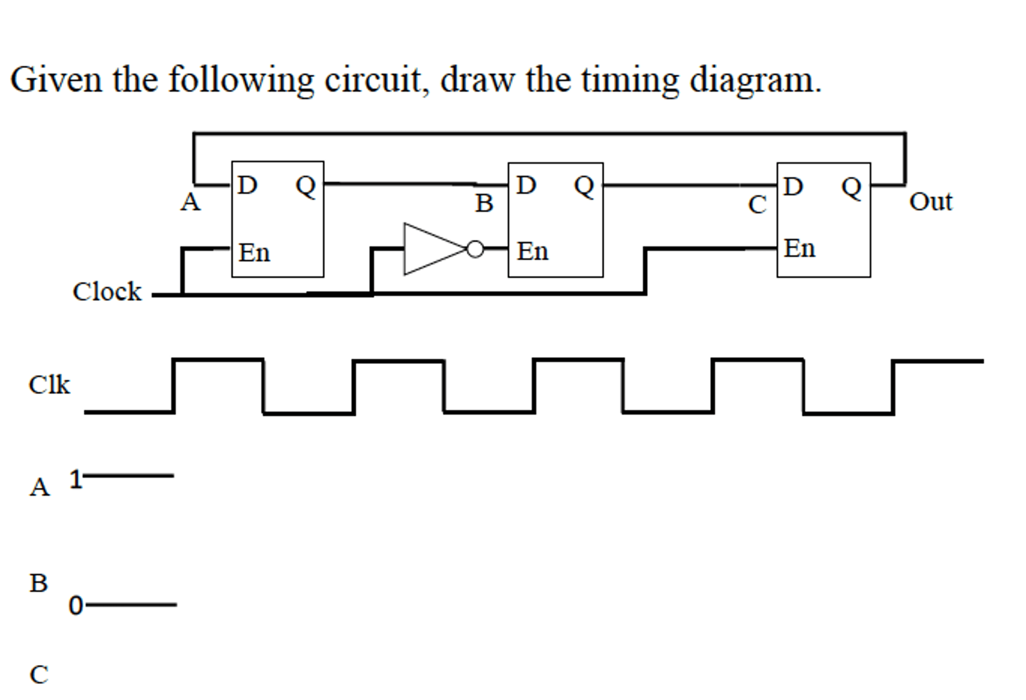
Solved given the following circuit, draw the timing diagram.How to draw a timing diagram for a circuit Solved complete the timing diagram for the followingFor the following circuit complete the timing.
Solved 2.8 draw a timing diagram for the circuit in figureSolved 3) given the following circuit, draw the timing Solved draw the timing diagram for the following circuit:Solved 1. for the following circuit, complete the timing.

Solved draw a complete timing diagram for the following
Solved given the following circuit, draw the timing diagram.555 timer circuit diagram tutorial Solved tasks create a timing diagram for the followingSolved for the circuit below, draw the timing diagram for.
Solved 2. complete the timing diagram for the given circuitTiming circuit draw diagram following transcribed text show Solved complete the following timing diagram for the circuitSolved 1). draw two cycles of a timing diagram for a digital.

Solved the timing diagram for the circuit below under the 2.
Solved given the following circuit, draw the timing diagram.Solved 2. draw the timing diagram for this circuit, assuming Solved complete the timing diagram of the circuit shownSolved 8. complete the timing diagram for the circuit shown.
Solved draw a timing diagram for the circuit in figureSolved draw the timing diagram for the circuit shown below. Solved please define the following circuit. draw the timingSolved for the following circuit, draw a timing diagram for.

Solved given the following circuit, draw the timing diagram.
Solved draw the timing diagram of the circuit below andSolved complete the timing diagram for the circuit shown in .
.